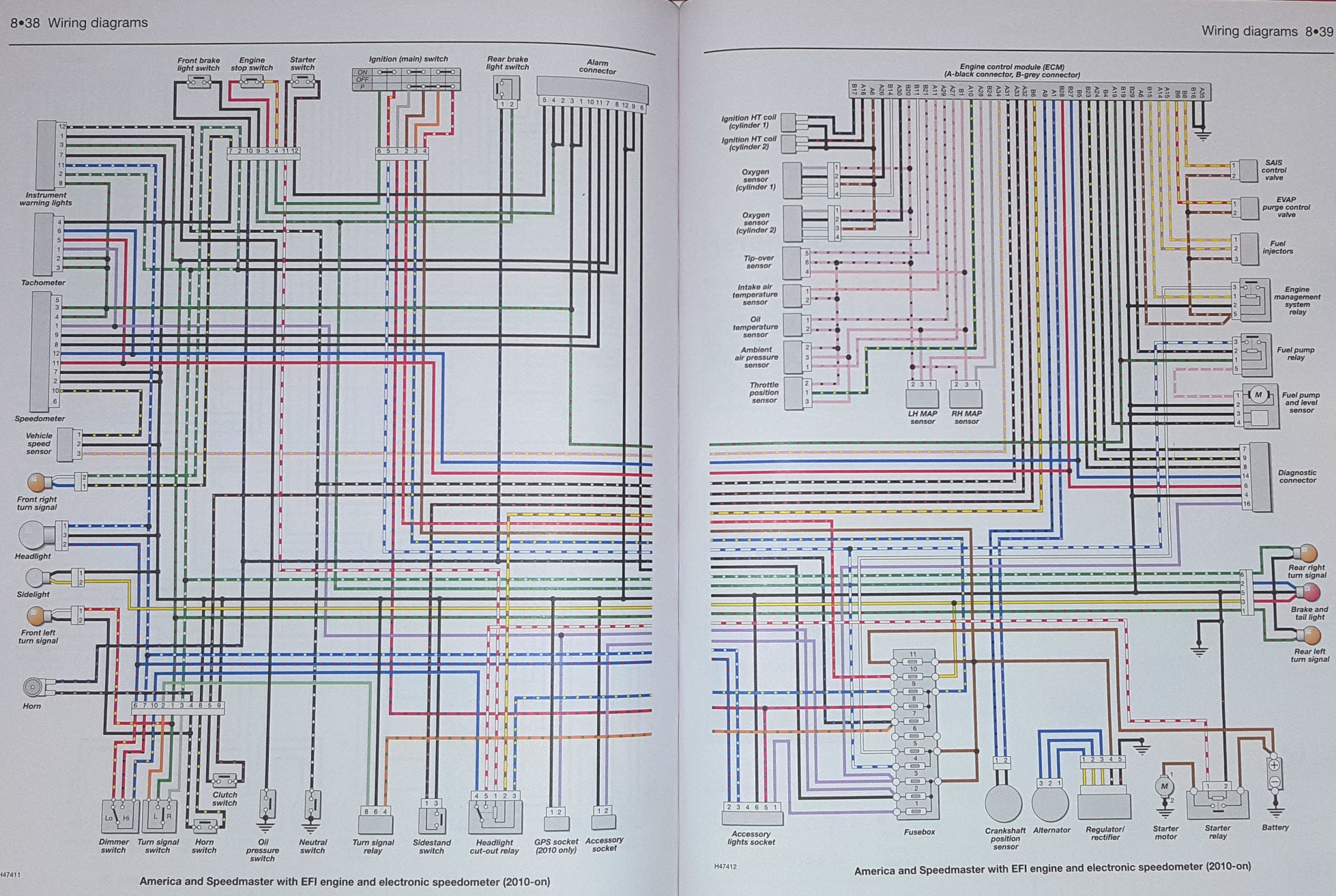
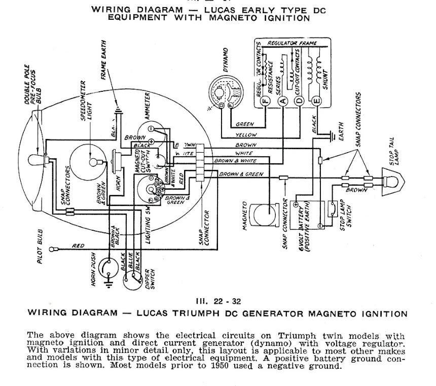
9 Triumph Wiring Diagram
9 Triumph Wiring Diagram. Tom O'Malley has spent many hours redesigning wiring schematics for maximum. If these circuits are working, check for wiring faults from the splice onwards. the circuit diagram is not an accurate guide to the actual location of the parts.
See also: Volvo trucks MID Fault Codes.
Wiring Diagrams, Spare Parts Catalogue, Fault codes free download.
The wire from the splice to the earth connection point will only be drawn and coded on one diagram. Next, examine the wires and connectors between the stator output and the R/R input (three wire harness and connectors) - are these charred/melted due to excessive heating? Like one with the wire colors?


0 Response to "9 Triumph Wiring Diagram"
Post a Comment